Key takeaways:
- A thermocouple which is a transducer which changes thermal energy into an electrical energy source, is created by joining different metals or semiconductors together to create a junction.
- The thermocouple relies on the concept of the Seebeck Effect, which defines that by joining dissimilar metals at one junction, a small measurable voltage will be produced by the two metals when the temperature of the junction is modified.
- A thermocouple measures an unknown temperature by measuring a known reference temperature.
- Thermocouples are popular temperature sensors because they have a wide temperature range, are rugged, and inexpensive.
- Differences in thermocouple types, is defined by the types of alloys used to produce their wire from, which is a single metal with another metal versus a metal to a semiconductor, or even a junction of a metal and a non-conductive polymer.

What is a Thermocouple?
Thermocouples are a particular kind of transducer that converts thermal energy to electrical energy. This apparatus is created by joining wires of different metals to form a junction.
As the temperature at the junction changes, a voltage develops that can be measured to find the temperature.
This device somehow operates on the basic principles of the Seebeck Effect, which states that when you form a junction from different metals, it generates a small, detectable voltage from a change in temperature at the junction. The generating voltage is related to the change in temperature and the metals involved directly.
A thermocouple is composed of two insulated wires (of different metals). The wires are connected to a measuring instrument.
A thermocouple can be used for both a monitoring safety device, and to monitor a process or specify the surrounding temperature of the machinery. As a result, the thermocouple maintains reliability over a wide range of applications by providing adequate temperature readings.
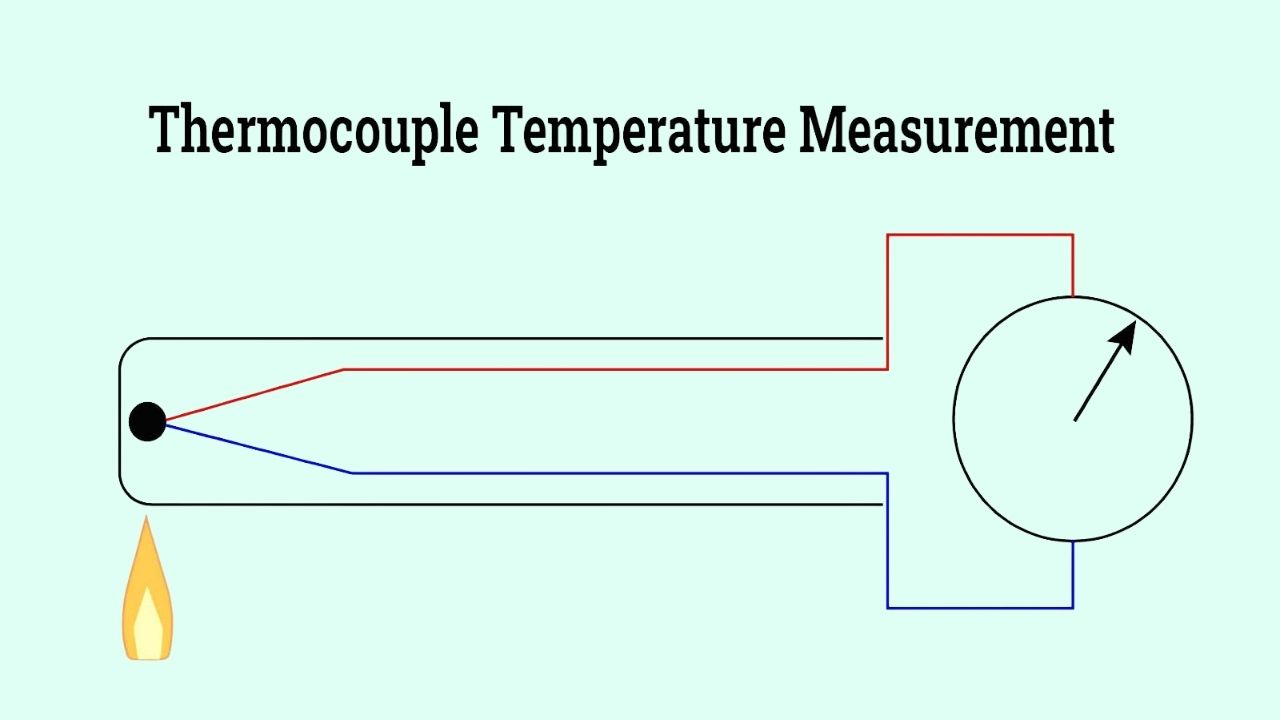
An illustration of how a thermocouple works is shown. As you can see, as the junction of the left side wires heat up, as the temperature increases you can see the change is shown on the gauge on the right.
Thermocouple assemblies are specifically designed for application in tough, extreme, and challenging environments. Selecting the right thermocouple involves considering factors such as temperature range, environmental conditions, and the type of material being measured.
Moreover, the thermocouple’s dimensions and form are customized to suit particular applications, ensuring optimal accuracy and responsiveness.
How Does a Thermocouple Work?
Thermocouples are temperature sensors widely employed in industrial and scientific contexts due to their low cost, robustness, flexibility, and large temperature range.
A thermocouple is a temperature sensor consisting of two dissimilar metal wires connected at the measuring point, called the hot or sensing junction, as well as where the end wires are joined as the reference, or cold junction.
The important components of the thermocouple temperature sensing principle rely on the generation of voltage (thermoelectric EMF) related to the temperature difference between these junctions.
By comparing the small voltage at the hot junction with the known temperature reference at the cold junction, a thermocouple accurately determines and monitors temperature change in a specific process or environment.
The thermoelectric principles relied upon by thermocouples include three thermodynamic phenomena: the Seebeck effect, Peltier effect, and Thomson effect.
It is important to be aware of these phenomena in setting conditions for thermocouple temperature measurement, selecting appropriate thermocouples for a specific application, and identifying process or system control measures in regards to, for example, manufacturing, chemical processing, and HVAC systems using thermocouples.
Seebeck Effect
The Seebeck effect is the primary operating principle of a thermocouple. When two different metals, typically types K (Nickel-Chromium/Nickel-Alumel), J (Iron/Constantan), or T (Copper/Constantan), are joined together at two junctions at different temperatures, a voltage (or electromotive force emf) appears across the wires.
The magnitudes and polarities of this emf depend on the temperature difference and the primary thermoelectric and conduction properties of the assembled metals.
Being able to produce a definitional voltage allows for the measurement of temperature differences quasi-instantaneously making thermocouples suitable for industrial temperature probes, furnace monitoring, and laboratory thermal measurements.
Peltier Effect
When current passes through two different metals, the Peltier effect is a cumulative effect that ultimately results in heating or cooling at the junction.
In the case of a thermocouple, the Peltier effect produces a voltage that corresponds to a temperature gradient across the two junctions. This voltage is measured and refers to a temperature reading or temperature difference.
The temperature distribution has been used in many forms of thermoelectric devices including temperature controllers.
One indication of the versatility of this technology, particularly when considering its scope in process automation and instrumentation, is the continued interaction of thermoelectric technology and innovations in this technology.
Thomson Effect
The Thomson effect complements the above principles by explaining the thermal energy absorption or release in a conductor carrying electric current with a temperature gradient along its length.
This effect contributes to the thermoelectric emf measured in a thermocouple circuit and must be considered for highly accurate temperature measurements, especially in environments with extended thermal gradients.
Understanding the Thomson effect helps select the optimal thermocouple wire material and calibration method to ensure measurement accuracy in industrial sensing applications.
Describing How a Thermocouple Works
The simple thermocouple circuit, sometimes refered to less accurately as a thermocouple junction in the image below, is composed of two wires (A and B) from different metals joined together at one end.
The join produces a hot (measuring) junction and the cold (reference) junction, which must be maintained at different temperatures to measure temperature accurately. A Peltier emf (E) will be generated across the circuit reflecting the temperature difference across these junctions.
When using a thermocouple, it is important to note that monitored temperature will be affected by both wire alloys and environmental exposure of the thermocouple sensor.
Electrons—the basis of heat and electrical conduction—allow the electrons to traverse from higher to low temperature within the metal conductive material under a temperature gradient.
The conduction of electrons represents thermal energy that converts into an electrical signal with a format that can be accurately measured as it is related to the temperature gradient.
This concept—based on the work of scientists such as Volta and Seebeck—is a principle which enables the common use of thermocouples in multiple industries for temperature measurement (eg. food processing, power generation, plastics manufacturing and metals).
The mV signal from a thermocouple is unique to the pairing of conductor materials, which are specified by IEC 60584 and ANSI/ASTM E230.
Standardization assures accuracy and interchangeability for different suppliers and manufacturers across the globe and allows the user to use thermocouples that will work with automation systems and electronic temperature controllers.
Accurate readings from thermocouples depend on cold junction compensation, frequently by just keeping the reference junction at 0°C by means of an ice bath or by simple advanced compensation chip.
This corrects for variations in ambient temperature so that you can have accurate readings for process control, industrial automation, and research-grade temperature logging.
There is generally more temperature accuracy in thermocouples with thicker wire, but this could introduce slower thermocouple response time, which should be taken into account when selecting a temperature sensor for high speed systems like kilns, extruders, or engine testing.
With both thermocouple junctions at the same temperature there is no potential and thus no current flow, a temperature differential begins to develop and the electro-motive force is established with the resultant voltage measured; the strength of the voltage depends on the thermoelectric coefficient of the metal types, and the junction temperature differential.
More advanced measurement equipment can learn this small signal with high-impedance voltmeters, high-accuracy potentiometers or data acquisition modules and a processed signal converts it into immediate temperature data for automated processes and for quality control and regulatory compliance purposes.
Thermocouples produce very small voltages—most commonly millivolt outputs—and therefore must be accurately measured. Measurement devices commonly used in process applications in industry that are used to measure thermocouples have high sensitivity to millivolt signals.
These measurement devices include high-sensitivity galvanometers, digital data loggers, and voltage-balancing potentiometers.
All of these products are often used for thermocouples because they have a capacity for amplifying measurements and then processing or interpreting the thermocouple signal accurately.
Furthermore, with the use of modern analog-to-digital converters with microcontrollers, temperature sensors can be incorporated even further into monitoring and control systems wiring which eliminates the concern of drift and enhances reliability for optimizing the process.
A potentiometer (“pot”) is usually used to calibrate a thermocouple system because you can compare the unknown thermoelectric voltage with a reference source. A pot’s high standard of precision allows for accurate and repeatable temperature measurement.
This measurement is important to keep pressures constant in a pressure vessel, heat exchanger or laboratory apparatus. A three-terminal variable resistor can also be used as a voltage divider in electronic circuits for signal conditioning or calibration.
A galvanometer measures very small electrical currents, and is essential for null detection or zero current—both are important for an accurate thermocouple calibration or sensor diagnostic capability.
This allows an engineer the ability to calibrate a temperature sensor, or tune a control loop to the required specifications, to help promote high accuracy in an array of commercial, laboratory, and field situations.
In absolute temperature measures, the cold/reference junction must be kept a known temperature in order for the sensor to render the best satisfactory output, regardless of the process.
The majority of commercially available thermocouple assemblies utilize a cold junction compensation chip immediately adjacent to the reference junction.
The purpose of the chip is to compensate for ambient temperature variations and provide an ambient level of precision for critical applications, for example: environmental calibration, pharmaceutical manufacture, and process engineering.
Immersion of a cold junction in a water or ice bath would allow for stabilization of the reading, which can be beneficial in applications requiring high precision and or research.
Ambient air temperature, humidity, and other factors can affect a thermocouple’s reference temperature. The use of reference junction compensation devices and software algorithms in automated systems mitigates this temperature impact.
This results in stringent measuring tolerances, making thermocouples useful as safety systems, environmental sensors, and closed-loop feedback in industrial automation.
Thermocouples are available in multiple types, temperatures, and calibrations (e.g., Type K, J, T, N, E, S, R, B) based on temperature range and chemical environment.
The aspects of accuracy, response time, chemical resistance, provision for mechanical durability, and compatibility with measuring instrumentation are some of the factors for consideration to select the correct thermocouple for your application.
Utilizing specialized thermocouple connectors and extension wires will minimize signal loss and variation in output when measuring temperature along your process line.
Extremely hazardous or high-pressure applications may require a protective sheath or advanced insulating materials for the thermocouple.
Using a Thermowell
A thermowell is a necessary accessory designed to protect a thermocouple from damaging process fluids, corrosive chemicals, and high-velocity/pressure flow.
Thermowells surround the sensing element in a closed-end tube or a solid bar-stock, and they are commonly used in refineries, power plants, petrochemical processing, and food/beverage production.
Thermowells provide a barrier to the thermocouple sensors and prolong the life of the thermocouple sensor, guarantee that there is going to be less downtime, and allow for safe and effective configure, or replace a thermocouple sensor while there are still processes at potentially high temperatures going on.
- Straight Thermowells
- Stepped Thermowells
- Tapered Thermowells
Thermowells may also be classified by the way they connect to a thermocouple or thermistor sensor. Common connection types include the following:
- Socket Welded Connections
- Flanged Connections
- Threaded Connections
- Weld-In Connections
When selecting a thermowell for your thermocouple or RTD (Resistance Temperature Detector), there are also many important considerations such as process temperature, pressure rating, chemical compatibility, and fluid velocity.
With several material choices, including stainless steel, Inconel, or Hastelloy, our selection of materials can affect the durability and corrosion resistance of thermowells. Correct sizing and insertion length are also important in order to provide fast and accurate process readings.
Consulting with a trusted thermowell manufacturer, or supplier, can help optimize system performance and protect your investment in the quality temperature measurement solutions we offer.
Maretial Used To Make Thermocouples
The differences between thermocouples arise from the types of alloys used to compose the wires. Each metal wire will vary based on the temperature range of measurements, environmental condition, required resistance to chemicals or contamination, and mechanical durability.
These key components represent the most user application of the most suitable sensor using thermocouples, whether the applications are industrial automation, laboratory research, or process control.
Thermocouples can be connected in three different configurations: exposed, ungrounded or insulated, and grounded.
1. Exposed Junction
The conductors are externally placed outside of the thermocouple sheath and it is exhibiting a fast response to temperature differences allowing for application in real time temperature applications, like applied research or fast response thermal profiling.
During application, an exposed junction is subject to damage from harsh environments, chemical exposure, and mechanical impact.
Exposed junction thermocouples are used in applications where fast thermal response is critical and there is little chance for sensor damage, like when measuring air or gas temperature in a clean non-corrosive housing application.
2. Grounded Junction
The wires are in contact and welded to the outer sheath making this thermocouple a sealed thermal coupling. The grounded junction is uninsulated and can be influenced by electro-magnetic interference (EMI) or environmental electromagnetic fields.
The grounded junction is the most commonly used design because of the fast response time, and strong heat transfer. Grounded junctions are a standard design applied in process piping for liquid immersion, gas flow or corrosive environments.
Grounded junction sensors are well suited for fast and accurate data to ensure process safety and usally the case for quality control.
3. Ungrounded Junction/Insulated
An insulated junction generally refers to a design where the sensing wires are insulated with magnesium oxide or some other insulating material so that they do not physically touch the sealed sheath – true Insulation without contact.
This design prevents the measurement wire from being impacted by environmental EMI and also will prevent ground loop interference.
When using an ungrounded thermocouple you are usually measuring in a sensitive electronic system, where any induced voltage interference will certainly affect the precise quality and accuracy of the temperature measurement.
While the overall response times are slower than exposed or grounded styles, often if low temperature response is required it is not essential.
Un-grounded thermocouples may be utilized to prevent sensitive measuring apparatus from induced voltages, or in any of these applications that includes a request for a degree of electrical isolation such as within electronic enclosures, engine testing, or laboratory instrumentation.
Thermocouple Sheath Material
A thermocouples can be placed in sheath that will protect it from atmosphere, chemicals, and prevent corrosion or oxidation, especially in harsh industrial situations.
The most commonly used sheath materials are stainless steel for good resistance to chemicals and durability, and Inconel and Incoloy, which are both registered trademarks of Special Metals Corporation.
Both types of sheaths are a kind of nickel alloy that show good resistance to oxidation at high temperatures. The sheath selection is critical for good life and accuracy of the sensor in harsh process conditions. The temperature ranges of the various types of sheaths are given in the table below.
Thermocouple Insulation
Vinyl
Vinyl insulation is inexpensive, flexible, and has average electrical performance, so it is an acceptable general-purpose material to use as thermocouple wire insulation in low-to-moderate temperatures. Vinyl is utilized where cost and ease of installation are more significant factors.
Teflon
Teflon (PTFE) is more costly because of its higher temperature rating and excellent chemical resistance, which means the product is robustly protected from aggressive chemicals and high humidity environments.
Teflon has excellent electrical properties, but its cut through resistance is low, which would require some other means of protection when cut throughing in an abrasive area.
Teflon’s high dielectric strength and non-stick properties make it ideal for laboratory, food processing, and pharmaceutical thermocouple applications.
Kapton
Kapton insulation has excellent physical, electrical, and mechanical properties across a wide temperature range and can be used in extreme heat and vibration environments, such as aerospace, automotive, and semiconductor production.
Additionally, Kapton can maintain mechanical strength in very harsh and dynamic environments, giving extra assurances for signal integrity in difficult locations.
Polyethylene
Polyethylene insulation is cheap and has good electrical properties; however, it is also very flammable. It is also stiffer than vinyl insulation. Polyethylene is best used in dry, low-temperature, and static applications where flexibility does not matter.
Fiberglass
Fiberglass insulation performs excellently in high-temperature service conditions and delivers dependable performance under environmental conditions with hot spots, thermal cycling, or operating furnace, kilns, foundries, and thermal processing.
The braided construction increases heat resistance and allows it to be used in rough applications that wouldn’t be suited for standard insulation.
Ceramic
Ceramic insulation is used in extreme environments, such as commercial ovens, and can track ambient temperatures in fireboxes, kilns, or grills. Ceramic insulates a large temperature span from -58°F to 2200°F (-50°C to 1204°C), and has both thermal shock and chemical stability. Ceramic insulation is ideal for use as an insulator in high-temperature industrial thermocouple probes.
Conductor Jacket
A conductor jacket can be added over the primary insulation layer for mechanical protection when there is a potential for abrasion or movement of the cable. For primary vinyl insulation this jacket is likely nylon; for vinyl or nylon insulation a polyethylene jacket may be used.
This jacketing provides a resistant mechanical barrier to electrical short circuits, increases overall durability and lifespan of the thermocouple assembly, and is a must in industrial automation or manufacturing environments.
Thermocouple Extension Wires
The extension wire connects the thermocouple sensor wire to the measuring instrument or data acquisition system. Extension wires are made of alloys of the same metals using the same thermal EMF properties as the thermocouples for long distance measurements.
Extension wires can be made from cheaper copper alloys, but they must maintain a closely matched thermal coefficient with thermocouple connectors, splices, and measuring instruments, otherwise undesirable measurement errors will occur.
The best thermocouple extension wire must be matched with other types of thermocouple components otherwise the precision temperature measurement of process control, HVAC, and testing laboratories will be compromised.
Thermocouple Circuitry
Standard single, average, thermopile, and delta are the four most common thermocouple circuit types. Learning how to configure the circuits is essential to get optimal performance out of thermal sensors, response time for sensors, and for accurate data collection in monitoring industrial processes or any temperature controlling system.
Standard
A standard single thermocouple consists of two different metal wires connected at a measuring junction. The resulting EMF is proportionate to the temperature difference, making this a basic method of temperature measurement in HVAC, scientific and process industries.
Average
Most thermocouple configurations are two or more thermocouples wired parallel to a common cold junction. If the thermocouples have the same resistance, the ratio of the resistance will equal the average EMF of the measurement point with respect to each thermocouple.
If there is a value of averaging the temperatures over a batch for a process with greater precision, this configuration makes sense. Examples include chemical reactors, environmental chambers, or, thermal mapping.
Thermopile
A thermopile uses multiple thermocouples in series, creating more output voltage and sensitivity. The total EMF of the thermopile is the sum of all junctions EMFs which is beneficial for applications that need higher signal strength and thermal imaging, like gas analyzers, infrared thermometers, and non-contact temperature sensors.
Delta
A delta thermocouple or differential thermocouple typically consists of two of the same wires to join to a dissimilar wire, with separate junctions at two different process points.
The output EMF output indicates the differential temperature between two locations being measured and allows for the direct measurement of a thermal gradient or heat loss monitoring in industrial processes.
In this arrangement, one of the thermocouple junctions must be ungrounded, and require specialized differential temperature instruments suited for accurately comparing the efficiencies of heat transfer and system performance.
Types of Thermocouple
Thermocouples exist in a variety of types for a wide range of temperature requirements and related processes. Each type of thermocouple is identified with a letter designation (Types including K, J, T, E, N, S, R, B, C) unique characteristics, including accuracy, temperature range, signal stability, oxidation resistance, and ruggedness.
Knowing the pros and cons of each type of thermocouple will help you select the proper model for your application, be it furnace control, food safety, cryogenics, or scientific instrumentation.
The most common thermocouple type is the grounded (rather than an ungrounded or conical) design, due to its fast response time (50% faster than ungrounded designs). The two sensor wires of the thermocouple are welded to the metal probe sheath, which promotes efficient heat transfer and more accurate readings in dynamic or fluid applications.
An ungrounded thermocouple is normally the second option, where the junctions from the sheath material are isolated utilizing either a ceramic or oxide insulator.
Isolation provides longer sensor use, greater immunity to electrical interference, and more compatible with new instrumentation—making them most desirable for laboratory analysis, electronics, and measuring temperature in dangerous or electrically noisy environments.
The least used thermocouple is the exposed type, where the sensing element is exposed to ambient conditions outside of the sheath. That way, it gives the best possible response time and allows for good measurement of surface temperature.
However, the exposed sensor is even more susceptible to damage than other thermocouple types. For this reason, exposed thermocouples will typically only be used in controlled settings or instances, like an R&D lab (or possibly clean process gases) where the probe protection requirement is minimal or important.
Base Metal Thermocouples
Base metal thermocouples are fine sensors of temperature in commercial, industrial, and laboratory situations. The most common base metal thermocouples, Types C, B, E, J, N K, R, T, and S, are made of metals like iron, copper, nickel, platinum, rhodium, chromel, etc.
All base metal thermocouple types consist of two dissimilar metallic conductors which are connected to form a measurement junction, with output voltage based on the difference in temperature between the two junctions that is a consequence of the Seebeck effect.
Type C
Type C thermocouples are made from tungsten and rhenium for high temperature applications (4200°F (2315°C)) in aerospace, metallurgical, and advanced ceramic processes. Type C thermocouples can sense temperature in hydrogen, inert, or vacuum atmospheres.
However, due to the inherent limitations of material usage, of using a thermocouple, a stable probe with sheaths for sensors made from either molybdenum, tantalum, or Inconel and insulators like alumina, hafnia, and magnesium oxide is always indicated for accurate sensor measurement.
The new temperature monitoring requirements brought up oxidation issues and failure of the thermocouples.
Type E
Type E thermocouples use chromel (nickel-chromium alloy) as the positive leg and constantan (copper-nickel alloy) as the negative leg. Type E’s physical range is from -330°F to 1600°F (-200°C to 870°C) and have excellent EMF versus temperature behavior.
Therefore, Type E thermocouples are a great choice for sub-zero and cryogenic temperature measurements as well as mid-range (0 or above) industrial heating applications.
Type E thermocouples’ high EMF output has the additional advantage of providing increased resolution when monitoring low temperature in a laboratory or in an environmental monitoring application.
Finally, in sulfur type environments that may damage the sensor use in protection tube is recommended.
Type J
Type J thermocouples utilize iron (positive leg) and constantan (negative leg) construction that give them versatility in oxidizing, vacuum, inert and reducing atmospheres.
They have a temperature span (32°F to 1000°F / 0°C to 760°C), low cost makes them common for plastic processes—such as injection molding—process heating, and temperature control systems.
If consistently used in humid or oxidizing situations, rusting of the iron conductor may shorten their overall life. Therefore it is always important to use protective coverings along with periodic monitoring for life expectancy.
Type K
A Type K thermocouple consists of chromel for the positive leg and alumel for the negative leg (aluminum, silicon, and manganese are combined with nickel). The typical temperature range is -300°F to 2300°F (-200°C to 1260°C).
Type K thermocouples are known as durable and reliable sensors for general purpose and industrial temperature measurements.
They are the most common thermocouples because of their relatively low price and reliable reference junction performance in oxidizing atmospheres and good signal stability.
Type K should be the first choice thermocouple for furnace use, automotive exhaust, gas turbines, and process engineering.
For example, cold junction reference errors depend on the cold junction temperature, and the metrology issues related to inert gas and low temperature use can significantly differ, so it is very important to verify accuracy through calibration.
Type N
Type N thermocouples have nicrosil (nickel-chromium-silicon) and nisil (nickel-silicon-magnesium) alloy conductors. type N thermocouples are stable and long lasting throughout their wide operating temperature range of 32°F to 2300°F (0°C to 1260°C).
They also have excellent oxidation resistance, green rot, hysteresis, and range of measurement which make Type N thermocouples desirable in the chemical processing, refining, and petrochemical industries, where thermal cycling is continuous, and reliability in the process is critical.
Type T
Type T thermocouples use copper for their positive leg and constantan for their negative leg. They are a great option for low-temperature, cryogenic and food processing applications.
With a positive temperature range of -330°F to +700°F (-200°C to +370°C), and enhanced temperature control in refrigeration and biomedical and chemical storage applications, Type T thermocouples allow for even more accurate temperature management in these environments.
Their strong anti-decomposition allows for longevity in the low temperature ranges, where accuracy is paramount and having the correct temperature is almost always critical to comply with safety protocols.
Noble Metal Thermocouples
Noble metal thermocouples, or platinum thermocouples include Types B, R, S, and P. These high accuracy, platinum or rhodium-based sensors are intended for use at high temperatures and are used to make very precise measurements of temperature.
Noble metal thermocouples tend to be more accurate, stable and longer lasting than standard thermocouples at elevated temperatures.
They are important within industries requiring high repeatability and stability in temperature, such as glass manufacturing, semiconductor fabrication, steel mills, and research and development labs.
Type B
The Type B thermocouple is designed for the highest temperature applications and has the highest temperature tolerance of the thermocouple types.
This thermocouple consists of Platinum (6% Rhodium) and Platinum (30% Rhodium), is stable/accurate to 3100°F (1700°C) and is perfect for glass and metals processing, high-temperature furnaces and precise heat treatment applications, etc.
Type R
Type R thermocouples are platinum, and platinum (13% rhodium) calibrated thermocouples, which provide excellent stability and safety at temperatures between -58°F to 2700°F (-50°C to 1450°C).
They are very accurate and, due to the higher rhodium, they are preferred in extreme process situations like sulfur recovery, glass, or pharmaceutical sterilization.
Type R thermocouples have the same temperature response and stability as Type S thermocouples, but they have increased durability in high and low-temperature process conditions.
Type S
Type S thermocouples, made from platinum and platinum (10% rhodium), are regularly used in high temperature applications in the BioTech, medical device sterilization, and pharmaceutical industries and in precision laboratory research.
Type S thermocouples are generally the industry standard for reference and calibration applications, and heat treatment process control where measurement reliability and reproducibility are critical. These thermocouples have a maximum temperature of 2700°F (1450°C) and remarkable stability over time.
Type P
Type P thermocouples exhibit a temperature response curve comparable to Type K thermocouples at high temperatures, but are made from precious metals providing better stability and resistance to oxidation.
Type P thermocouples can be used in oxidizing atmospheres up to 2300°F (1260°C). When installed into a monitoring or measuring system, a Type K extension wire is most probably used to maintain the signal and measurement accuracy, even in unforgiving industrial temperature sensing applications.
Uses for a Thermocouple
Thermocouples are a common temperature sensor because they have a large temperature span, are durable, inexpensive, and used in many applications, therefore, home appliances, industrial processes, electric power generation, furnace monitoring and control (e.g. hot-spot detection), food and beverage processing, automotive sensors (exhaust gas temperature, combustion chamber, catalytic converter), aircraft engines, rocket motors, and spacecraft.
Thermocouples are compact, have a fast response time, and are less sensitive to shock and vibration than other temperature sensors, which is a great advantage for accurate temperature control and measurement.
Here is a description of a few of the different applications of thermocouples:
Thermocouple Applications
Food Production
Thermocouples are great for the food industry because of their quick and accurate temperature readings. They can be utilized at many points in production to make sure the food is cooked or stored appropriately.
Most food production thermocouples are two-piece units consisting of: a handheld readout and the detachable probe. The probe houses 2 wires connected at the tip.
There are flat-headed probes for measuring surface temperature, and needle probes for internal temperature and air temperature in ovens.
Extruders
Extruders produce parts under high temperature and pressure and often necessitate precise temperature measurement. The thermocouple sensor tip must be positioned to take the temperature of the molten plastic.
Thermocouples with thermocouple sensor tips allow for direct temperature measurement and are not affected by heat transfer delay associated with the probe design.
While many sensors maintain precision and rapid response capability in these extreme temperatures, they often use a Type K thermocouple probe to meet the rapid response needs of the application.
Furnace
A pilot light ignites the burner of a furnace. The thermocouple is responsible for checking that there is always a flame. If the thermocouple does not detect a flame, it shuts off the gas to the unit so that gas cannot accumulate inside the furnace.
This safety measure not only reduces the risk of dangerous accumulation of gas in the furnace, but ensures that a furnace receives gas only when a pilot light is ignited.
Molten Metal
A thermocouple made of molten metal is used in non-ferrous metal applications, and can measure temperatures up to 1250°C.
Molten metal thermocouples are used to measure and monitor temperature in various stages of the liquid metals processes, including melt preparation, holding, degassing, and casting.
The high operating temperature and resilience make molten metal thermocouples key to quality and integrity of metal processing.
Gas Appliances
The thermocouple on a gas appliance is a key safety feature. The thermocouple detects pilot light temperature, and this provides a voltage to keep the gas valve open to allow gas to flow to the burner.
If for any reason the pilot flame goes out, the voltage goes down, the gas valve closes, and no gas is allowed to escape. The main usefulness of thermocouples relates to the safety of protecting people against the hazards of having gas released if the pilot flame goes out.
High Pressure Boiler
Finding appropriate instrumentation for a high-pressure source is difficult because of the extreme temperature and heavy vibrations that you will face.
Typically in these high-pressure, high-temperature situations, you are looking at resistance thermometers (RTDs) and thermocouples should be your temperature sensors of choice, but the thermocouple is often the most suitable solution because of its durability, wide temperature range, and superior function in a high pressure and vibration environment.
There are two thermocouple configurations specifically suited for high pressure applications that are pictured below:
- Conventional – where the thermocouple assembly is either threaded or flanged.
- Lens-ring – the thermocouple is mounted in a metallic lens-ring gasket that is compressed between two flanges to make the seal. It makes the seal with the lens-ring gasket and it can be used for both mounting and access to the process for a measurement.
How to Test a Thermocouple
Thermocouples are reliable and long-lasting, but they can fail over time, so thermocouples should undergo periodic checks.
Even though there are many different styles of thermocouples, they all work on the same principle two connected wires, with one wire serving as the reference junction and the other wire as the hot or measuring junction.
The efficiency of a thermocouple is tested using a multimeter. Below is a description of a multimeter and a procedure to test a thermocouple.
Multimeter Readings
Multimeters come in many shapes and sizes. They may all look different, but they all have some basic symbols to identify their uses.
- Volts V
- Amps A
- Ohms Ω
They may also have prefixes.
- μ – Micron or one millionth
- m – milli or one thousandth
- k – kilo or one thousand
- M – Mega or one million
There will also be settings for AC or DC.
Some multimeter include a continuity beeper that beeps when it detects a closed circuit. A continuity check is used to test for a complete path for current. Below is an example of a multimeter with a continuity beeper.
Testing a Thermocouple (step by step process)
Step 1
A multimeter can read ohms, which measures resistance to the flow of current in an electrical circuit. For example, conductors such as silver, copper, gold, and aluminum have low resistance and insulators have high resistance.
Conductor metals are used in making thermocouple wires. As thermocouples create millivolt signals, the multimeter you will use to test must be hypersensitive.
Step 2
In order to do the resistance test, unplug the thermocouple from the application. Move the multimeter to ohms.
Put one lead on the side of the thermocouple and the other lead on the end which was inserted to the application. Assuming the thermocouple has proper continuity, the multimeter should indicate a small resistance.
Step 3
The first step of the open circuit test is to unplug the thermocouple from the application. Change the multimeter to millivolt mode.
Touch one lead to the side of the thermocouple, and the other lead to the opposite end. Using a torch, heat the end that was in the application. The millivolt reading should be in range for the thermocouple being tested.
Step 4
The closed circuit test needs a thermocouple adapter. Insert the adapter into the application, then screw the thermocouple into the adapter. Connect one lead of the multimeter to the screw of the adapter and connect the other lead to the exposed end of the thermocouple.
Turn the application on and the multimeter will show your reading in millivolts. If the reading is unacceptable, the thermocouple must be removed and replaced.
How to Read a Thermocouple
Thermocouples are an inexpensive and accurate means of measuring many temperature ranges. Thermocouples are often used in: boilers, water heaters, ovens, and airplane engines.
Before you read a thermocouple, you must first understand a thermocouple reference table. Each thermocouple type has its own reference table. Below is a small sample of the reference table for a Type K thermocouple.
| °C | 0 | 1 | 2 | 3 | 4 | 5 | 6 | 7 | 8 | 9 | 10 |
| Thermoelectric Voltage in mV | |||||||||||
| -270 | -6.458 | ||||||||||
| -260 | -6.411 | -6.444 | -6.446 | -6.448 | -6.450 | -6.452 | -6.453 | -6.455 | -6.456 | -6.457 | -6.458 |
| -250 | -6.404 | -6.408 | -6.413 | -6.417 | -6.421 | -6.425 | -6.429 | -6.432 | -6.435 | -6.438 | -6.441 |
| -240 | -6.344 | -6.351 | -6.358 | -6.364 | -6.370 | -6.377 | -6.382 | -6.388 | -6.393 | -6.399 | -6.404 |
| -230 | -6.262 | -6.271 | -6.280 | -6.289 | -6.297 | -6.306 | -6.314 | -6.322 | -6.329 | -6.337 | -6.344 |
| -220 | -6.158 | -6.170 | -6.181 | -6.192 | -6.202 | -6.213 | -6.223 | -6.233 | -6.243 | -6.252 | -6.262 |
| -210 | -6.035 | -6.048 | -6.061 | -6.074 | -6.087 | -6.099 | -6.111 | -6.123 | -6.135 | -6.147 | -6.158 |
| -200 | -5.891 | -5.907 | -5.922 | -5.936 | -5.951 | -5.965 | -5.980 | -5.994 | -6.007 | -6.021 | -6.035 |
| -190 | -5.730 | -5.747 | -5.763 | -5.780 | -5.797 | -5.813 | -5.829 | -5.845 | -5.861 | -5.876 | -5.891 |
| -180 | -5.550 | -5.569 | -5.588 | -5.606 | -5.624 | -5.642 | -5.660 | -5.678 | -5.695 | -5.713 | -5.730 |
| -170 | -5.354 | -5.374 | -5.395 | -5.415 | -5.435 | -5.454 | -5.474 | -5.493 | -5.512 | -5.531 | -5.550 |
| -160 | -5.141 | -5.163 | -5.185 | -5.207 | -5.228 | -5.250 | -5.271 | -5.292 | -5.313 | -5.333 | -5.354 |
| -150 | -4.913 | -4.936 | -4.960 | -4.983 | -5.006 | -5.029 | -5.052 | -5.074 | -5.097 | -5.119 | -5.141 |
| -140 | -4.669 | -4.694 | -4.719 | -4.744 | -4.768 | -4.793 | -4.817 | -4.841 | -4.865 | -4.889 | -4.913 |
| -130 | -4.411 | -4.437 | -4.463 | -4.490 | -4.516 | -4.542 | -4.567 | -4.593 | -4.618 | -4.644 | -4.669 |
| -120 | -4.138 | -4.166 | -4.194 | -4.221 | -4.249 | -4.276 | -4.303 | -4.330 | -4.357 | -4.384 | -4.411 |
| -110 | -3.852 | -3.882 | -3.911 | -3.939 | -3.968 | -3.997 | -4.025 | -4.054 | -4.082 | -4.110 | -4.138 |
| -100 | -3.554 | -3.584 | -3.614 | -3.645 | -3.675 | -3.705 | -3.734 | -3.764 | -3.794 | -3.823 | -3.852 |
| -90 | -3.243 | -3.274 | -3.306 | -3.337 | -3.368 | -3.400 | -3.431 | -3.462 | -3.492 | -3.523 | -3.554 |
| -80 | -2.920 | -2.953 | -2.986 | -3.018 | -3.050 | -3.083 | -3.115 | -3.147 | -3.179 | -3.211 | -3.243 |
| -70 | -2.587 | -2.620 | -2.654 | -2.688 | -2.721 | -2.755 | -2.788 | -2.821 | -2.854 | -2.887 | -2.920 |
| -60 | -2.243 | -2.278 | -2.312 | -2.347 | -2.382 | -2.416 | -2.450 | -2.485 | -2.519 | -2.553 | -2.587 |
| -50 | -1.889 | -1.925 | -1.961 | -1.996 | -2.032 | -2.067 | -2.103 | -2.138 | -2.173 | -2.208 | -2.243 |
| -40 | -1.527 | -1.564 | -1.600 | -1.637 | -1.673 | -1.709 | -1.745 | -1.782 | -1.818 | -1.854 | -1.889 |
| -30 | -1.156 | -1.194 | -1.231 | -1.268 | -1.305 | -1.343 | -1.380 | -1.417 | -1.453 | -1.490 | -1.527 |
| -20 | -0.778 | -0.816 | -0.854 | -0.892 | -0.930 | -0.968 | -1.006 | -1.043 | -1.081 | -1.119 | -1.156 |
| -10 | -0.392 | -0.431 | -0.470 | -0.508 | -0.547 | -0.586 | -0.624 | -0.663 | -0.701 | -0.739 | -0.778 |
| 0 | 0.000 | -0.039 | -0.079 | -0.118 | -0.157 | -0.197 | -0.236 | -0.275 | -0.314 | -0.353 | -0.392 |
The leftmost column of the table contains increments of ten in temperature, the right-side portion of the table shows the intermediate distances in one increment. For instance, in the above table, -280°F is the third line from the top.
If your thermocouple is reading -284°F, you could go to the table, find -280°F, and follow it to the right to find what number is displayed under the 4 column. The numbers displayed under this section of the table (to the right of column) are the millivolt readings for temperature.
A thermocouple, and every reference junction on the thermocouple, may experience temperature changes that could affect reading accuracy. However, the reference temperature must remain relatively constant to provide accurate readings.
By placing the reference junction in water, the water will keep the reference temperature relatively stable.
A reference junction compensator will also accomplish this function; compensators will account for any ambient temperature variations. Below is a simple representation of a compensation calculator.
Thermocouple Laws
Homogenous Materials
A wire is homogeneous it is uniform in all physical and chemical respects, and in a thermocouple wire, there will not be any emf developed no matter what physical state the wire has undergone (i.e. thickness, temperature etc).
A thermocouple requires two metals to develop a thermocouple; otherwise, the thermocouple will not develop an emf based on differences in temperature.
Intermediate Materials
If all junctions in a thermocouple circuit are at the same temperature, the sum of the emfs will equal zero. Adding different metals to the circuit does not change or affect the voltage generated as long as all junctions are at the same temperature.
For example, whether you attach copper leads to connect a thermocouple to measurement equipment or to a piece of wire or use solder to connect the metals it will have no effect on what is measured.
This will be true because the added junctions need to be at the same temperature as the junctions in the circuit for a thermocouple to provide an accurate temperature reading when attached to a digital multimeters or electrical devices.
Successive or Intermediate Temperatures
A thermocouple produces an emf when two different metals are exposed to different temperatures. A thermocouple can be calibrated with a reference temperature and then connected, in good emf fashion, to other wires with the same thermoelectric properties.
So, if additional wires can be added to the circuit with no change in the emf generated by the thermocouple, the main requirement is that the temperature differences between the thermocouple junctions remain constant.