When it comes to connecting two mechanical parts, engineers generally rely on two main types of joints: permanent joints, such as welding, and temporary joints, like cotter joints or fasteners.
In situations where quick assembly and straightforward maintenance are priorities, temporary joints are usually the preferred option for manufacturers. For instance, if you need to link two shafts that are far apart to transfer power efficiently, a temporary joint is the go-to solution.
This approach not only simplifies the assembly process but also makes future repairs and adjustments much more manageable.
What is a Cotter Joint?
A cotter joint sometimes referred to as a socket and spigot joint is a practical way to temporarily connect two rods that are aligned along the same axis. In this setup, one of the rods features a spigot (a sort of projection), which is designed to fit neatly inside a socket on the other rod.
Both the socket and the spigot are slotted, and when these slots line up, a cotter (essentially a flat, wedge-shaped piece of metal) can be pushed through to lock the rods together securely.
Cotter joints are particularly useful when you need to handle axial loads meaning the force can be either pulling the rods apart (tension) or pushing them together (compression).
While this type of joint does provide some resistance against one rod turning relative to the other, it isn’t meant for applications where the rods (or shafts) are rotating.
The reason is straightforward: the cotter itself isn’t balanced, so if you try to use this joint for rotating shafts, there’s a real risk that the cotter could work loose over time due to vibration and the effects of centrifugal force.
Typically, a cotter joint assembly involves three main parts:
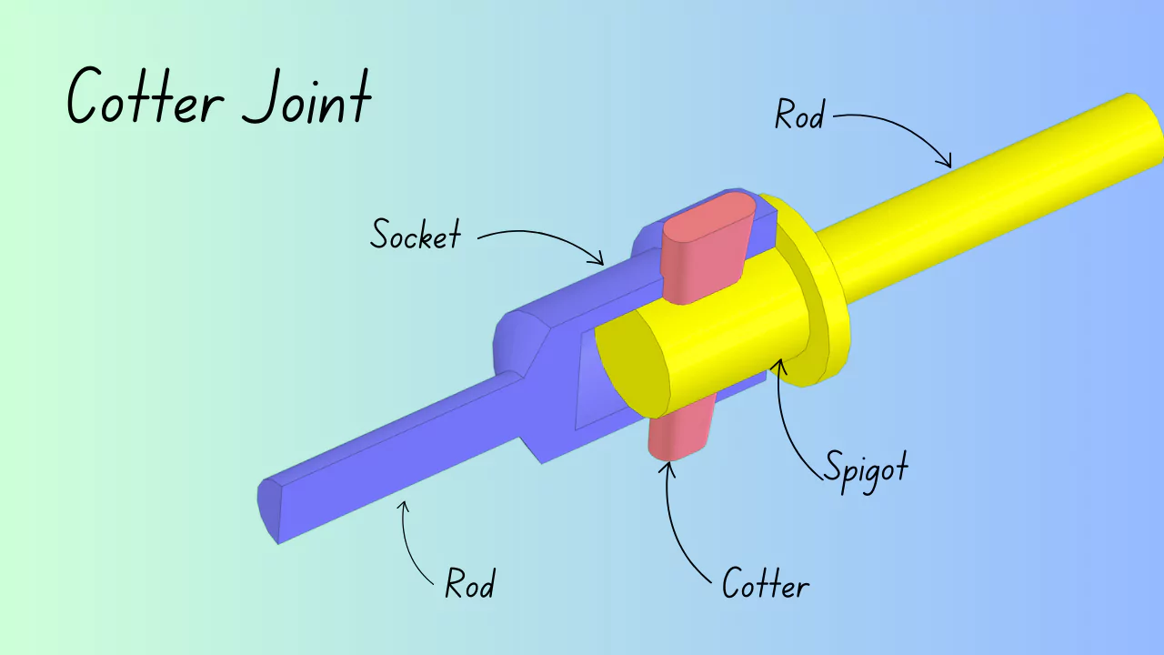
- Spigot: This is the male component in the joint. You’ll notice it has a rectangular slot, designed so the cotter can pass right through. The spigot also includes a collar, which serves to support and rest up against the end of the socket.
- Socket: Acting as the female part of the joint, the socket mirrors the spigot’s rectangular slot, allowing the cotter to go through. The main feature here is a circular opening where the spigot fits snugly.
- Cotter: A cotter is basically a metal piece shaped like a wedge. Its job is to link together two parts that don’t rotate relative to each other, locking them securely in place.
A cotter is essentially a flat, wedge-shaped piece of metal, commonly used to connect two rods so they can transfer force without rotating relative to each other. The force being transmitted along these rods can be either axial tension or compression.
What makes the cotter unique is how it’s installed. It’s driven into a tapered slot that holds it securely in place, all thanks to the wedge effect created by the taper. In practice, the taper on a typical cotter usually falls somewhere between 1 in 48 and 1 in 24.
This particular taper serves two important purposes. Firstly, it makes removing the cotter quite straightforward disassembling the joint is hardly ever a hassle.
Secondly, the taper helps keep the joint tight, reducing the risk of any loosening during operation. In other words, a properly fitted cotter is both easy to work with and reliable at keeping things firmly in place.
Types of Cotter Joint
Following are the three types of cotter joints to connect two rods by a cotter:
- Socket and spigot cotter joint
- Sleeve and cotter joint
- Gib and Cotter joint
1. Socket and spigot cotter joint
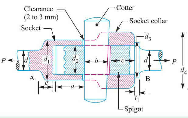
A cotter joint, often referred to as a socket and spigot joint, is a practical technique for temporarily connecting two rods that share the same axis. In this arrangement, one rod is shaped with a socket at its end, while the other rod is formed with a spigot, which fits snugly inside the socket.
Both the socket and the spigot are machined with a rectangular slot. Through this slot, a flat piece of metal called a cotter is inserted and driven tight, effectively locking the two rods together but allowing for easy disassembly when needed.
Typically, the forces acting on this joint are axial, meaning they run along the length of the rods. However, these forces can switch direction, so the cotter joint must be engineered to withstand both pulling (tensile) and pushing (compressive) loads. The compressive force, in particular, is absorbed by a collar located on the spigot.
2. Sleeve and Cotter Joint
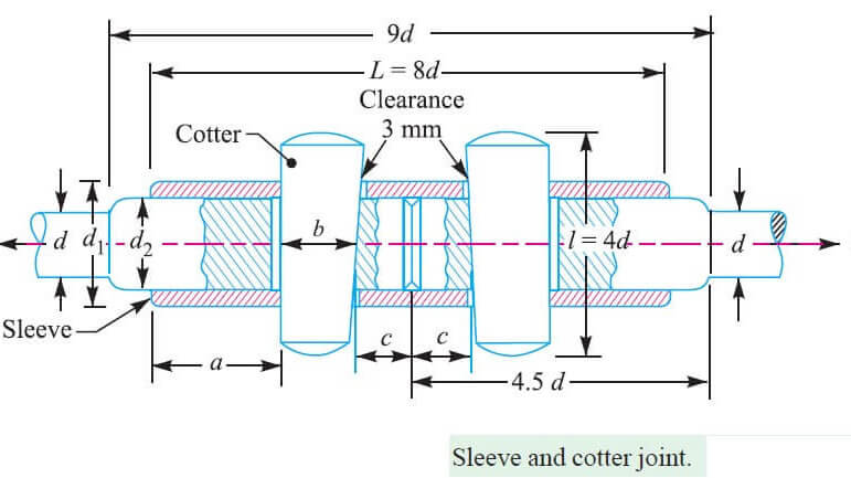
A sleeve and cotter joint is a straightforward yet effective method for connecting two coaxial cylindrical rods of similar size. The joint is composed of a sleeve, which fits over the ends of the rods, and two wedge-shaped cotters that are tapered typically with a taper ratio of 1 in 24.
To accommodate these cotters, corresponding slots are machined into both the sleeve and the rods themselves.
When assembling the joint, the cotters are inserted into their respective slots with their tapered sides facing each other. This specific orientation is essential for the joint’s function.
As the cotters are driven in, the clearance between them is carefully managed so that the rods are drawn tightly together, resulting in a secure and firm connection.
One reason for the popularity of the sleeve and cotter joint is its simplicity. Not only is it easy to assemble and take apart, but it is also robust enough to handle both tensile and compressive forces. While it is most often used to join cylindrical rods, it can also serve to connect pipes or tubes of similar dimensions.
However, this joint has certain limitations. It is not suitable for joining rectangular rods or cylindrical rods of differing diameters.
Additionally, the sleeve and cotter joint does not permit any angular misalignment between the connected rods. It is also unsuitable for applications where the connected cylindrical members need to rotate relative to one another.
3. Gib and Cotter joint
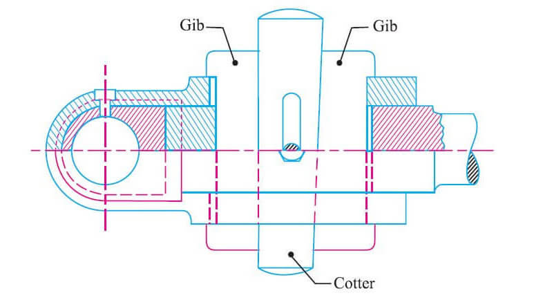
A gib and cotter joint is frequently found at the strap end or big end of a connecting rod. When only a cotter is used meaning without a gib friction between the cotter ends and the inner slot of the strap can force the strap edges to flare outward. This can compromise the joint’s integrity.
To counteract this, a gib is added. The gib keeps the ends of the strap firmly together, preventing them from opening up. Another benefit is that it offers a broader bearing surface for the cotter, which means the cotter slides more smoothly and holds more securely.
With this arrangement, the friction from the cotter is less likely to loosen the joint over time. It also allows for the use of parallel holes in the assembly, which can be an advantage during fabrication and maintenance.
Gib and cotter joints are particularly suited for rods that have square or rectangular cross-sections. In these joints, the end of one rod fits neatly into a strap-shaped end of the other rod.
A gib is used alongside the cotter for these types of connections. While a gib looks similar to a cotter, it is distinguished by having two gib heads at each end. Importantly, the gib and cotter are made to the same thickness, ensuring a snug, reliable fit.
- In setups where a single gib is involved, you’ll typically find the cotter designed with just one side tapered, and interestingly, the gib is always fitted on the outside.
- On the other hand, if the assembly uses two gibs, the cotter is made with both sides tapered to match the arrangement.
- Now and then, to keep the cotter from working loose, a small set screw is inserted through the rod so it presses directly against the cotter, effectively locking everything in place.
Application of Cotter Joint
Following are the cotter joint applications:
- Connecting Piston Rods in a Crosshead (Steam Engines): One of the classic applications for a cotter joint is linking the piston rods to the crosshead in steam engines. This setup handles both push and pull forces, ensuring reliable transmission of motion.
- Extending the Piston Rod: When there’s a need to attach an extension to a piston rod, a cotter joint provides a straightforward and sturdy solution.
- Bicycle Pedal and Sprocket Wheel Connection: If you’ve ever looked closely at older bicycles, you’ll notice cotter joints being used to attach the pedals to the sprocket wheels—a practical example outside of heavy machinery.
- Foundation Bolts: Cotter joints can also be found in foundation bolts, where they help anchor machinery securely to its base.
- Valve Mechanism (Slide Spindle and Fork Connection): In valve mechanisms, particularly in engines, these joints connect the slide spindle to the fork, playing a key role in controlling movement within the system.
- Joining Flywheel Halves (Cotter and Dowel Arrangement): For joining the two halves of a flywheel, a combination of cotter and dowel ensures a tight and stable connection, critical for the flywheel’s operation.
- Tail Rod and Piston Rod (Wet Air Pump): Cotter joints are also used to link a tail rod to the piston rod, especially in wet air pumps, where they need to handle repeated motion and substantial forces.
- Connecting Two Rods of Equal Diameter (Axial Forces): Whenever two rods of equal diameter are subjected to axial forces and need to be connected, a cotter joint often fits the bill due to its simplicity and effectiveness.
- Automobile Engines (Piston Rod Extension to Connecting Rod): In automotive engineering, cotter joints commonly connect the piston rod’s extension to the connecting rod within the crosshead. This connection is vital for translating linear piston movement into rotational motion.
- Historical Applications (Steam Engines and Mine Pumps): Historically, cotter joints have been indispensable for connecting rods in both steam engines and the pumps used to drain mines. Their durability and reliability made them a staple of early mechanical design.
Advantages of Cotter joints
- One of the convenient features of cotter joints is how straightforward they are to assemble. Every time you take them apart and put them back together, the components line up in the exact same way, which makes maintenance hassle-free.
- These joints are also quite versatile; you can use them to connect pipes and tubes of the same type without any complications.
- When it comes to putting cotter joint parts together or taking them apart, the process is refreshingly simple—there’s no need for any special tools or extra muscle. It’s a quick job, whether you’re assembling or dismantling.
- In terms of production, cotter joints are pretty easy to make, and if you ever need a replacement, you’ll have no trouble finding them in the market.
- Another practical advantage is their rigidity. Cotter joints can handle both pulling (tensile) and pushing (compressive) forces without losing their shape or strength.
Disadvantages of cotter joints
- Cotter joint isn’t suitable for connecting rectangular rods or cylindrical rods that aren’t the same size. If you try to use it in these cases, it simply won’t work as intended.
- Sleeve and cotter joints, when not used with properly matched cylindrical members, actually allow rotation. So if the rods aren’t a good fit or aren’t cylindrical, you’ll end up with unwanted movement at the joint.
Failure of Cotter joint
When the cotter joint tightened in the socket and spigot slot, it was exposed to shear stresses. Then if the cotter is loose, the cotter will bent. The various modes of failure in cotter joint are discussed below:
- Failure of the rods in tension
- Failure of the spigot in tension across the weakest section
- Failure of the rod or cotter in crushing
- Failure of the socket in tension across the slot
- Failure of cotter in shear
- Failure of the socket collar in crushing
- Failure of socket end in shearing
- Failure of rod end in shear
- Failure of spigot collar in crushing
- Failure of the spigot collar in shearing
- Failure of cotter in bending
In this article we learn about the cotter joint, this is one type of mechanical joint and, also known as a socket and spigot joint, is a method of temporarily joining two coaxial rods.
One rod is fitted with a spigot, which fits inside a socket on one end of the other rod. Slots in the socket and the spigot align so that a cotter can be inserted to lock the two rods together.
FAQs
What is the difference between a pin joint and a cotter joint?
A cotter joint is useful for joining two rods/shafts that are axial for the transmission of motion from one shaft to other. The pin joint has a little more flexibility as compared to a cotter joint and is used to join two rods/shafts that are either axial or at any angle in same plane
Is cotter joint a permanent fastening?
The joining of any two mechanical parts is carried out by two types of joints: Permanent joints like welding and Temporary joints like cotter joints and fasteners. Now, if a part requires to have faster assembly and easy maintenance, temporary joints are the best choice for manufacturers.
What are the three types of cotter pins?
Standard: Popular, versatile style with straight prongs for easy installation. T-Head: Ideal for applications when limited clearance is required. Wedgefast: Features an integrated clasp that spreads the prongs during installation for applications with limited access.
What is the advantage of a knuckle joint over a cotter joint?
1. High tensile pressures can be accommodated by knuckle joints.
2. Even with varying material thickness and tensile strength, it can provide high precision.
3. They offer exceptional mechanical strength.
4. They are uncomplicated to install and have a straightforward construction.
5. The knuckle joint is simple to install and disassemble.
6. The knuckle joint’s structure is simple to produce.
7. This joint has fewer components, which makes it more dependable and less expensive.
8. This permits the transfer of angular momentum between the rods and is primarily given for longer tool life.
What are the rules for cotter pins?
The cotter pin should fit neatly into the hole, with very little side play. The following general rules apply to cotter pin safetying. Do not bend the prong over the bolt end beyond the bolt diameter.