What is Chip formation?
Chip formation is the central feature of mechanical cutting processes like those that occur in saws, lathes, and milling cutters. Many understanding the principles and engineering facets of chip formation is a fundamental component for anyone directly involved in the design and development of chip removal machines and their associated cutting tools.
Chip formation as an academic interest emerged during World War II and continued in the years after. The significant cutting advancements and the improved cutting speed and capability of machines, particularly with the introduction of high-speed steel cutters for metalworking, supported this evolution.
Where chip formation is described, most engineers use a three-part model established by Franz. Although this model relates more to machine tool design, any practitioners in other areas, such as woodworking, will find value in the established framework and in some case, they may even require a more complex means to describe the process of chip formation when the simple reference will not suffice.

Types of Chips
1. Continuous Chips
When machining ductile materials, we can expect continuous chips to be produced at rapid cutting speeds since there will be reduced friction contact between the tool and the work material.
The production of continuous chips are due to the great amount of plastic deformation that occurs at the tool-chip interface; this excessive plastic deformation basically ‘shears off’ the chip from the cutting zone to flow with minimal interruption in thickness.
Continuous chips are primarily produced with ductile materials, such as mild steel and copper, and continuous chips are interesting because they maintain a consistent width for their entire length, which tends to yield a consistent surface finish on the finished part – a positive outcome.
However, there can be a practical disadvantage to continuous chips – sometimes these chips can be cumbersome, and create problems in the machining process of the material.
There are many factors that lead to the formation of this type of chip, the primary factors being:
- The machined material is ductile mild steel
- The tool has a significant rake angle.
- The cutting speed is high.
- There is limited friction or contact area between the chip and tool interface.
- There is a small depth of cut.
Advantages
The generation of continuous chips during machining has the following benefits
- Improved surface finish in the ductile material.
- Less heat production because there is less friction between tool face and chip.
- Reduced power consumption.
- Increased tool life from lowered wear and tear.
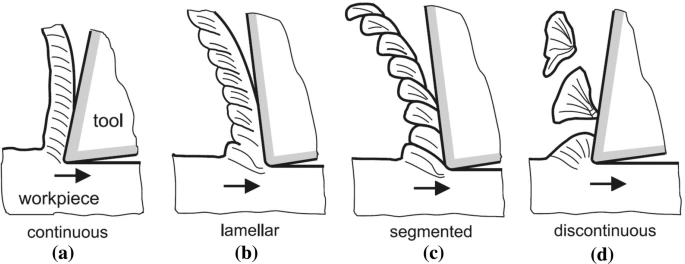
2. Discontinuous Chips
Chips that break apart instead of forming a continuous strand during machining, are defined as discontinuous chips.
This type of chip typically occurs during the machining of materials that are brittle or hard metals – for example brass, bronze and cast iron.
However, it’s not only the metal being machined that is important; even ductile materials can form discontinuous chips if there are excessive friction forces acting between the cutting tool and workpiece.
Discontinuous chips are usually undesirable as they produce a rougher surface finish and can increase machining times.
The following conditions effectively generate discontinuous chips:
- Low feed rate.
- Small rake angle of the tool.
- High cutting speed.
- High friction forces acting at the chip tool interface.
- Excess depth of cut.
Advantages
The discontinuous chips produced by brittle materials create a smoother surface on the finished workpiece, prolonging the life of the cutting tool while decreasing overall power consumption while machining.
Disadvantages
However, discontinuous chips often form while machining ductile materials resulting in a rougher surface finish which is detrimental to tool wear due to increased wear rates and often affecting tool durability.
3. Continuous Chips with Built-Up Edges
When cutting ductile materials, one commonly sees the formation of continuous chips that produce built-up edges primarily when taking cut with larger feeds or depths and with high temperatures and pressures at the chip-tool interface. Built-up edges typically are formed from high cutting forces and friction.
Although these chips behave like normal continuous chips, the surfaces will be rougher because of the built-up material on the tool edge. Workpiece material can adhere or even weld to the cutting edge of the tool.
You may wonder how it produces.
A built-up edge results when the chip continues to move upward and friction at the cutting interface (tool and chip) increases.
The friction creates considerable heat, important heat is created at the nose of the tool, and due to the high temperature and pressure, some of the compressed metal can effectively be welded to the tool, resulting in a built-up edge.
Now, any chip that develops, continues to flow over the welded interface and a portion of the built-up edge can break off from it and will be carried away with the bed-ups edge chips; the remaining built-up edge will remain on the workpiece surface leaving a thicker and rougher finish.
Why do Continuous Chips with BUE occur when your machine?
- By using the ductile material during machining.
- Due to the smaller rake angle of the tool.
- The tool has a slow cutting speed.
- There may have been no coolant so that will increase friction between the chip-tool faces.
- The chip thickness is high.
- Due to the high temperature between tool and workpiece.
- High rate of feed of the tool.
Advantages
One notable benefit of built-up edge (BUE) formation is the existence of a protective layer, which inhibits the cutting tool from excessive friction/ heat when machining. A BUE forms a barrier to prevent frictional heat, and also high temperature. This may increase wear life.
Disadvantages
Nonetheless, the existence of these chips is not without limitations. Their formation quite frequently can cause a rougher surface finish on the workpiece. Also, BUE can have an affect on both rake angle and cutting forces.
FAQs
What is the chip formation process?
1) Chip formation involves the shear deformation of work material to form a chip as new material is exposed during cutting.
2) There are four basic types of chips in machining: continuous, discontinuous, serrated, and those with built-up edge (BUE)
Why is chip formation important?
Good chip formation produces spiral-shaped chips and guarantees good tool life, easy chip handling and evacuation, good surface quality and a stable, reliable, efficient cutting process. In short, a good chip must be an easy-to-handle size and require minimal effort to generate.
What are the conditions for chip formation?
Many factors influence chip formation, especially including workpiece material. The process of metal cutting includes plastic deformation of workpiece material, which is then sheared off. Elastic and plastic material behavior play a decisive role in this process.
How do you control chip formation?
The most practical way to influence chip formation is to modify cutting conditions, which can be very easy and effective to change. The basic cutting condition to adjust is chip thickness ratio or slenderness.
How is chip created?
The process of creating a computer chip starts with the purification of the silicon. Then, the silicon is sliced into a silicon cylinder. Finally, the cylinders are exposed to a doping process, which adds special impurities to the silicon substrate. The transistors are the most essential part of a computer.