Engineering has always recognized the existence of imperfections and working with tolerances. Tolerance is the term that defines the degree of acceptance before imperfection. Thus, any tolerance should only be defined for a certain application, process, and material used.
Imperfections are known as any difference regarding the project of the structure. They are inevitable in engineering, but not all of them should be treated as unacceptable.
This article deals with such deviations in relation to welds.
What are Welding Defects?
Welding Defects can be defined as the irregularities formed in the given weld metal due to the wrong welding process or incorrect welding patterns, etc. The defect may differ from the desired weld bead shape, size, and intended quality.
Basically, welding defects include any flaws that compromise the quality of the weld. They can be defined as occurring any time there is a deviation in the size and shape of the metal structure that affects technical and design requirements.
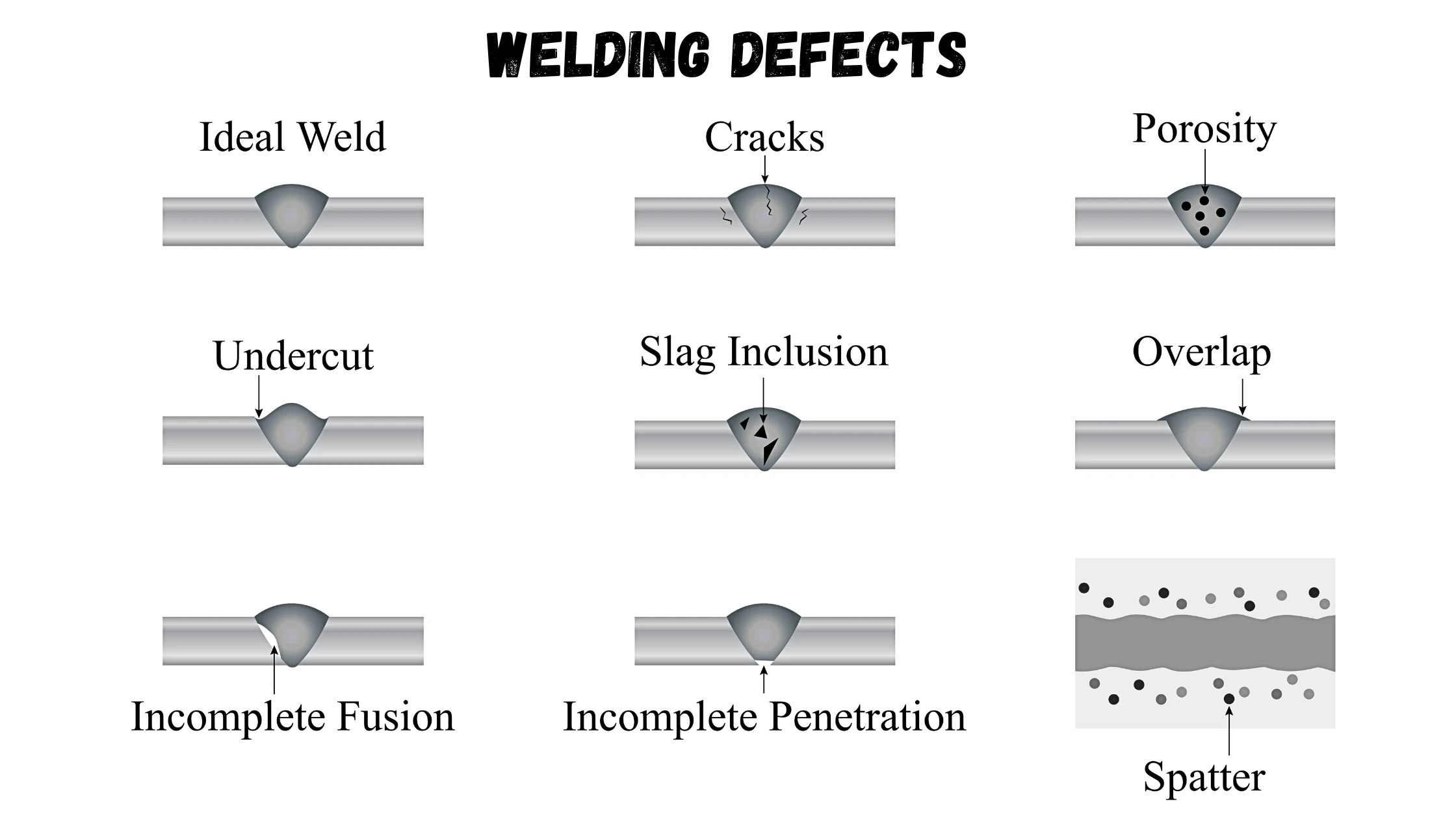
A defect can occur at any stage of the welding process. They can be either internal or external. Internal defects are not visible. They include defects such as slag inclusion, incomplete penetration, and incomplete fusion.
External defects are more easily detectable because they can be seen on the metal surface itself. They include cracks, undercuts, porosity, spatter, and overlaps. Let’s take a look at some of these external defects.
What are weld discontinuities?
Discontinuity is an interruption in the typical physical structure of a material that sharply changes its properties. Thus, the simple variation of properties does not characterize a discontinuity. However, only discontinuities that exceed the tolerance limit should be considered welding defects.
Thus, a weld with a particular crack can be considered approved or disapproved for different applications.
What are common weld defects?
Among the discontinuities related to the welding process, one can mention 15 types:
- Cracks
- Undercut
- Porosity
- Spatter
- Overlap
- Slag Inclusions
- Lack Of Penetration
- Incomplete Fusion
- Warpage
- Burn Through
- Wormholes
- Crater
- Lamellar Tearing
- Laminations
- Delamination
1. Cracks
Cracks are the most common welding defect. There is almost no way a weld can meet any standard if it has a crack. They are imperfections produced due to the local rupture from the effects of stresses and cooling. They are often significant because their geometry creates a large stress concentration at the crack’s tip.
Therefore, the weldment is prone to fracture. Welding cracks can come in various sizes, shapes, and types, including:
- Longitudinal
- Transverse
- Crater
- Radiating
- Branching

There are different types of cracks, depending on the temperature at which they occur:
- Hot cracks: These cracks can occur during the welding process when the process uses intensive heat, generally when the temperature rises to more than 10,000 degrees Celsius (18,032 degrees Fahrenheit). They can also occur during crystallization when the weld has used high temperatures.
- Cold cracks: These appear a few hours or days after the weld is complete during the cooling down or solidification process. They are most common when welding steel and generally because the steel itself is deformed.
- Crater cracks: These occur at the end of the welding process before the operator finishes a pass on the weld joint. They usually form near the end of the weld. When the weld pool cools and solidifies, it needs to have enough volume to overcome the shrinkage of the weld metal. Otherwise, it will form a crater crack.
Causes For Cracks:
- Use of hydrogen when welding ferrous metals.
- Residual stress is caused by solidification shrinkage.
- Base metal contamination.
- High welding speed but low current.
- No preheat before starting welding.
- Poor joint design.
- A high content of sulfur and carbon in the metal.
Remedies For Cracks:
- Preheat the metal as required.
- Provide proper cooling of the weld area.
- Use proper joint design.
- Remove impurities.
- Use appropriate metal.
- Make sure to weld a sufficient sectional area.
- Use proper welding speed and amperage current.
- To prevent crater cracks, make sure that the crater is properly filled.
2. Undercut
Undercut refers to the groove or depression that forms along the edge of the weld bead, where the base metal has melted but has not been adequately filled by the filler metal. This results in a weakened joint that is prone to cracking, corrosion, or failure, particularly under cyclic loading conditions.

Undercut welding defect runs parallel to the weldment, causing a loss in thickness. As a result, the weld joint becomes more susceptible to fatigue. The types of undercuts are:
- Continuous undercut
- Inter-run undercut
- Intermediate undercut
Causes for undercut:
- Too high weld current.
- Too fast weld speed.
- The use of an incorrect angle, will direct more heat to free edges.
- The electrode is too large.
- Incorrect usage of gas shielding.
- Incorrect filler metal.
- Poor weld technique.
Remedies for undercut:
- Use proper electrode angle.
- Reduce the arc length.
- Reduce the electrode’s travel speed, but it also shouldn’t be too slow.
- Choose shielding gas with the correct composition for the material type you’ll be welding.
- Use of proper electrode angle, with more heat directed towards thicker components.
- Use of proper current, reducing it when approaching thinner areas and free edges.
- Choose a correct welding technique that doesn’t involve excessive weaving.
- Use the multi-pass technique
3. Porosity
Porosity is the formation of holes in the weld pool resulting from gas bubbles that cannot escape. It is usually one of the common welding defects when using shielding gas, which is present in welding techniques such as TIG and stick welding. Absence, lack, or too much shielding gas may lead to metal contamination, which reduces the strength of the weld.

On the other hand, severe versions of porosity come in the form of blow holes or pits when large gas bubbles get trapped in the weld pool. Additionally, smaller gas molecules can blend with the weld metal, forming an impure compound.
Causes for porosity:
- Inadequate electrode deoxidant.
- Using a longer arc.
- The presence of moisture.
- Improper gas shield.
- Incorrect surface treatment.
- Use of too high gas flow.
- Contaminated surface.
- Presence of rust, paint, grease or oil.
Remedies for porosity:
- Clean the materials before you begin welding.
- Use dry electrodes and materials.
- Use correct arc distance.
- Check the gas flow meter and make sure that it’s optimized as required with proper with pressure and flow settings.
- Reduce arc travel speed, which will allow the gases to escape.
- Use the right electrodes.
- Use a proper weld technique.
4. Spatter

Spatters are small metal particles ejected from the welding arc. These tiny particles are splashed or scattered on the base metal during Arc welding, tack welding, or Gas welding. It also occurs during Mig welding, albeit rarely. These types of welding defects often stick to the length of the weld bead. You may also find them in joint designs.
Spatters that accumulate in the nozzle may detach and damage the weld bead. They can also cause accidents for handlers if the spatter projections are sharp.
Causes for Spatter:
- The running amperage is too high.
- The voltage setting is too low.
- The work angle of the electrode is too steep.
- The surface is contaminated.
- The arc is too long.
- Incorrect polarity.
- Erratic wire feeding.
Remedies for Spatter:
- Clean surfaces before welding.
- Reduce the arc length.
- Adjust the weld current.
- Increase the electrode angle.
- Use proper polarity.
- Make sure you don’t have any feeding issues.
5. Overlap

Overlap, also called cold lap, occurs in fusion welds when weld deposits are larger than the joint is conditioned to accept. The weld metal then flows over the surface of the base metal without fusing to it, along the toe of the weld bead.
It generally occurs on the horizontal leg of a horizontal fillet weld under extreme conditions. It can also occur on both sides of flat-positioned capping passes. With GMAW, overlap occurs when using too much electrode extension to deposit metal at low power.
Misdirecting the arc into the vertical leg and keeping the electrode nearly vertical will also cause overlap. To prevent overlap, the fillet weld must be correctly sized to less than 3/8 in. (9.5 mm), and the arc must be properly manipulated.
Causes for overlap:
- Improper welding technique.
- By using large electrodes this defect may occur.
- High welding current
Remedies for overlap:
- Using a proper technique for welding.
- Use small electrode.
- Less welding currents.
6. Slag Inclusion

Slags are dangerous substances that appear as byproducts of shielded metal arc welding, stick welding, flux-core arc welding, submerged arc welding, etc. Slag inclusions occur as trapped impurities between welding turns or on the surface of the weldment.
They occur when you use a flux (solid shielding material) during welding. When the flux melts on the surface of the weld or within the weld region, these welding defects can occur. The presence of slags affects the metal’s weldability and toughness. As a result, they decrease the structural performance of the weld.
Causes for Slag Inclusion:
- Improper cleaning.
- The weld speed is too fast.
- Not cleaning the weld pass before starting a new one.
- Incorrect welding angle.
- The weld pool cools down too fast.
- Welding current is too low.
Remedies for Slag Inclusion:
- Increase current density.
- Reduce rapid cooling.
- Adjust the electrode angle.
- Remove any slag from the previous bead.
- Adjust the welding speed.
7. Lack of Penetration

Incomplete Penetration occurs when the root of the weld bead does not reach the root of the joint to weld the opposite surface in the part. To correct this discontinuity, you can increase the current, decrease the welding speed, or change the joint geometry.
Causes for Lack of Penetration:
- There was too much space between the metal you’re welding together.
- You’re moving the bead too quickly, which doesn’t allow enough metal to be deposited in the joint.
- You’re using a too-low amperage setting, which results in the current not being strong enough to properly melt the metal.
- Large electrode diameter.
- Misalignment.
- Improper joint.
Remedies for Lack of Penetration:
- Use proper joint geometry.
- Use a properly sized electrode.
- Reduce arc travel speed.
- Choose proper welding current.
- Check for proper alignment.
8. Incomplete Fusion

Incomplete Fusion occurs with localized lack of fusion, either at the joint edge or at the face of the previously deposited strand. To correct this discontinuity, you can increase the current, decrease the welding speed, change the joint geometry or use some artifice to avoid magnetic blowing.
Causes for incomplete fusion:
- Low heat input.
- Surface contamination.
- Electrode angle is incorrect.
- The electrode diameter is incorrect for the material thickness you’re welding.
- Travel speed is too fast.
- The weld pool is too large and it runs ahead of the arc.
Remedies for incomplete fusion:
- Use a sufficiently high welding current with the appropriate arc voltage.
- Before you begin welding, clean the metal.
- Avoid molten pool from flooding the arc.
- Use correct electrode diameter and angle.
- Reduce deposition rates
9. Warpage

Warpage is an unwanted change in the shape and position of the metal parts. It happens when the heat usage is wrong and is caused by the contraction/expansion of the welded parts. You will find this welding defect on thinner weld plates because their surface areas cannot sufficiently dissipate heat.
Cause for Warpage:
- Varying temperature gradients during welding
- Using an incorrect welding order
- Slow arc travel speed
- Too many welds pass with small diameter electrodes
- High residual stress in the metal plate to be welded
Remedies for warpage:
- Using a proper torch angle may reduce the stress on the metal
- Using a small electrode may also decrease the crater.
- Use a proper technique.
10. Burn Through

An open hole is exposed when the welding process accidentally penetrates the whole thickness of the base metal, creating a burn-through or melt-through. This is one of the common weld defects when welding thin metals.
Causes of Burn-Through:
- Too high welder settings for thick metal stocks
- Significantly large gaps between metal pieces
- The too-slow movement of the torch
- Using incorrect wire sizes
Remedies for burn-through:
- Avoid using too high a current or welder setting.
- Prevent having excessive gaps between metal plates.
- Ensure that the travel speed is optimal and not too slow. Travel speed varies with the choice of welding technique. Arc travel speed between 14 to 19 inches per minute is ideal for MIG welding. In contrast, the ideal travel speed for orbital welding equipment is 4 to 10 IPM.
- Avoid large bevel angles.
- Use tight wire sizes.
- Ensure adequate metal clamping and hold-down.
11. Wormholes
Wormholes are elongated or tubular cavities caused by excessive entrapped gas. Wormholes are detected by RT where they have the appearance of sharply defined dark shadows of rounded or elongated contour, depending on the orientation of the wormholes.
Wormhole Prevention. Wormholes are prevented by methods that are similar to those that prevent porosity.
12. Crater
Craters are special kinds of cracks that occur after the welding process before the completion of weld joints. It often occurs due to improper filling of the crater before breaking the arc. This leads to faster cooling of the outer edges than the crater. Insufficient volume of the weld may prevent it from overcoming metal shrinkage. As a result, there is the formation of a crater crack welding defect.
Causes of Crater:
- Improper filling of the crater
- Incorrect torch angle
- Wrong choice of welding technique
Remedies for Crater:
- Ensure proper filling of the crater.
- Use a suitable torch angle for lowering stress on the metal.
- Use a small electrode.
- Choose the correct welding technique.
13. Lamellar Tearing
Lamellar tearing welding defect usually occurs at the bottom of welded rolled steel plates. Their distinguishing feature is a crack with a terraced appearance. Lamellar tearing occurs when there is a thermal contraction within the steel plate. It can also be found outside heat-affected zones, often parallel to weld fusion boundaries.
Causes of Lamellar Tearing:
- Weld metal deposits on surfaces with optimum cohesion
- Improper material selection and welding orientation
Remedies for Lamellar Tearing:
- Ensure welding is done at the end of the fabrication.
- Select the best quality materials and use the right welding orientation.

14. Laminations
Laminations differ from lamellar tearing because they are more extensive and involve thicker layers of nonmetallic contaminants. Located toward the center of the plate, laminations are caused by insufficient crop[1]ping (removal of defects) of the pipe in ingots.
The slag and oxides in the pipe are rolled out with the steel, producing the lamination. Laminations can also be caused when the ingot is rolled at too low of a temperature or pressure.
15. Delamination
When laminations intersect a joint being welded, the heat and stresses of the weld may cause some laminations to become delaminated.
Contamination of the weld metal may occur if the lamination contains large amounts of slag, mill scale, dirt, or other undesirable materials. Such contamination can cause wormhole porosity or lack-of-fusion defects.
The problems associated with delaminations are not easily corrected. If a thick plate is installed in a compression load, then an effective solution can be to weld over the lamination to seal it. A better solution is to replace the steel.
How to Detect Welding Defects
Testing methods are a great way to check if the welding patterns meet specific criteria. It allows us to find the causes and remedies for why welding defects occur. While it takes some time, it ensures that the welds are safe and risk-free.

There are two standard procedures for finding defects in a weld metal:
Non-Destructive Testing
Non-destructive testing allows us to observe discontinuities in the weld incurring no damage. This testing method is essential in high-speed production wherein a sample is tested from a batch.
Non-destructive testing and evaluation is usually done by utilising visual inspection, liquid penetrants, magnetic particles, eddy currents, ultrasonics, acoustics, emissions or radiography.
Destructive Testing
Destructive testing acquires information by subjecting the finished projects to strenuous methods until it reaches their limits. Some cases require destructive testing in addition to non-destructive tests in order to reduce weld defects in production significantly.
Some destructive methods used to identify the limits of the weld metal are acid etch, guided bend, free bend, back bend, nick break, and tensile strength.
How to Distinguish Between Weld Discontinuity and Weld Defects
Weld discontinuities are interruptions in the normal flow of a weldment’s structure. This may either be in the parent metal or the weld metal, and they occur due to wrong welding methods or welding patterns. These irregularities often differ from desired weld bead sizes, shapes, and intended quality. They can also be internal or external.
The following points distinguish welding defects from discontinuities:
- A weld would become a defect if the quality control department completely rejects the product.
- A discontinuity can survive field tests, but a defect cannot.
- Discontinuities often have a defined list of acceptable limits before rejection.
- Weld discontinuities are usually within acceptable manufacturing error margins, but defects must be repaired or rejected.
That said, if discontinuities exceed stated project limits, they may become a weld defect. Ultimately, it is vital to inspect welding processes using efficient methods.
Sources: